First, principle
The use of advanced technologies such as central processing unit (CPU) and large-scale integrated circuits (ICs) constitutes an automated test equipment. The operation process is fully automated, and test data can be printed on the micro-printer equipped with a panel. This equipment is stable compared to common instruments and similar types of instruments. Good performance, high precision, and good operability. The device has multiple test operation modes in the test operation. The main features are:
Test method: 6 consecutive tests, automatic averaging, and 6 test data and averages printed by the panel printer.
Single automatic test mode: Automatically complete 1 test and print out single test data.
This machine adopts AC reversible motor to push the voltage regulator through the step-up transformer at a uniform speed of 3 kV/sec. When the oil sample is broken down, the protection system automatically cuts off the boost power supply circuit, and the protection circuit provides an interruption to the system. Signal, after the system responds, executes the test breakdown breakdown program, its main operation content:
The four-digit digital tube flashes continuously for 8 times to indicate the breakdown of the test oil;
Record test data;
Program-controlled automatic zero return operation. After returning to zero, according to the number of trials to identify whether to proceed with the next test cycle or automatically exit the test state.
A, LYZJ-V automatic oil dielectric strength tester Test report outlines   Describe
LYZJ-V automatic oil dielectric strength tester test report is our scientific research and technical personnel, according to the national standard GB507-86 and the line standard DL-474 · 4-92DL/T596-1996 relevant regulations, to play its own advantages, after many Field trials and long-term unremitting efforts, well-developed high-precision, all-digital industrial instruments. The machine is easy to operate and beautiful in appearance. Due to the adoption of fully automatic digital microcomputer control, the measurement accuracy is high, the anti-interference ability is strong, and it is safe and reliable.
Second, LYZJ-V automatic oil dielectric strength tester test report instrument characteristics
1. The instrument is controlled by a large-capacity single-chip microcomputer and the operation is stable and reliable;
2. The device has a wide range of watchdog circuits to eliminate the crash phenomenon;
3. A variety of operating options, instrument program with GB1986 , GB2002 two national standard methods and custom operations, can adapt to a variety of different user options;
4. The instrument oil cup adopts special glass casting once to prevent the occurrence of oil leakage and other interference phenomena.
5. The unique high-pressure sampling design of the instrument allows the test value to enter the A/D converter directly, avoiding the error caused in the analog circuit and making the measurement result more accurate;
6. The instrument has functions such as over-current protection, over-voltage protection, short-circuit protection, etc., and it has strong anti-interference ability and good electromagnetic compatibility.
7. portable structure, easy to move, both inside and outside the home is very convenient.
Third, technical indicators
1. Booster capacity 1.5 kVA
2. Boost Speed 2.0 kV / s, 2.5 kV / s, 3.0 kV / s, 3.5 kV / s optional fourth gear
3. Output voltage 0 ~ 80 kV
4. Power distortion rate < 4%
5. Display mode Large-screen LCD Chinese character display
6. Electrode Clearance Standard 2.5 mm
7. Dimensions 430 mm × 410 mm × 412 mm
8. The instrument weight 29 kg ;
Fourth, the use of conditions
1. Ambient temperature 0 to 40 °C
2. Relative humidity ≤ 85%
3 working power AC 220V ± 10%
4. Power frequency 50 ± 5 Hz
5. Power consumption < 200
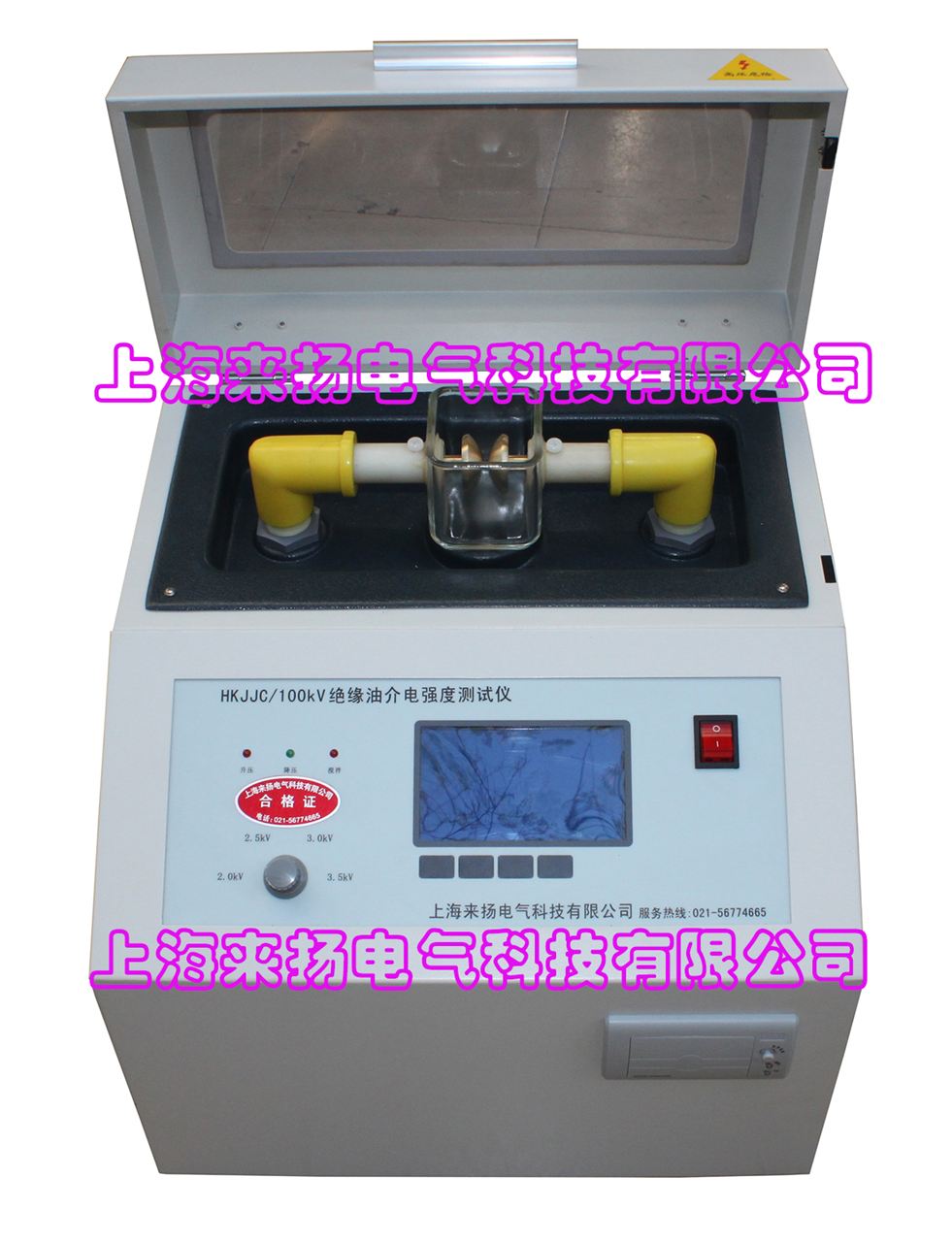
V. Chassis and panel parts description
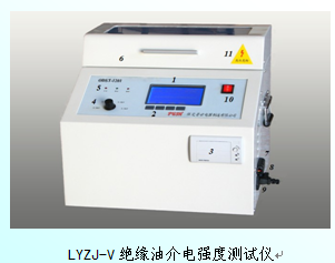
LYZJ-V Dielectric Oil Dielectric Strength Tester
1. LCD screen; 2. Function keys; 3. Printer; 4. Boost rate switching switch ;
6. Oil cup cover; 7. Temperature and humidity sensor; 8. Ground post; 9. Power jack; 10. Power switch; 11. High voltage safety sign
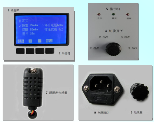
1. LCD screen        Display date, time, operating parameters, test results, operation menu prompts and other relevant information;
2. Function keys select settings operating parameters;
3. The printer prints the average of single and multiple test results;
4. switch to select different boost rates;
5. When the indicator light is on, it indicates that the relevant operation steps are in progress;
6. Put the oil cup into or out after opening the lid of the oil cup and close it before testing;
7. The temperature and humidity sensors measure Celsius and relative humidity and convert them to digital signals for display;
8. Ground column reliable ground connection column;
9. The power socket is well connected with the AC 220V 50Hz power cable;
10. The power switch controls the power of the instrument;
11. High pressure mark indicates high pressure dangerous triangle mark.
Sixth, the operation step diagram
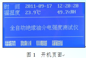
1. Plug in the power cord, turn on the power switch, and the LCD screen displays the boot page (Figure 1 )

Figure 1 boot page
2. In the page of Figure 1 , press the setup button to enter the next page (Figure 2 );

3. In the Figure 2 page, press  select  Key to move the cursor  To GB 1986 , press  confirm  The key can enter the national standard 1986 setting sub page (Figure 3 ).

Under the page in Figure 3 , press the SELECT button to move the cursor to the stop voltage, press + or - to set the stop voltage  The default value is 80 kV and the selectable range is 10 kV to 80 kV (delta Δ = 10 kV ). After selecting, press  confirm  The key returns to the boot page, press  Start  Key to test.
If there is no reliable grounding, the instrument will show grounding! And send an alarm sound, then you should turn off the power, and then re-operation after connecting the ground. If there is no or no conditions to install the ground wire, you can press any key to skip, without affecting the test results.
4. Under the page in Figure 2 , press the SELECT button to move the cursor to the GB2002 and press the ENTER key to enter the GB 2002 setting subpage. The operation under this page is basically the same as that of the GB1986 subpage. For details , please refer to the relevant contents of Figure 6 .
5. Under the page in Figure 2 , press the Select key to move the cursor to the time setting and press the Enter key to enter the time setting subpage (Figure 4 ).

press  select  Press the key to move the cursor to the year, month, day, hour, and minute, press the + or - key to select the specific value, press the confirmation key to confirm, and return to the boot page;
6. In Figure 2 page, press the Select key to move the cursor to the custom setting , press the Enter key to enter the Custom Settings sub-page (Figure 5 );
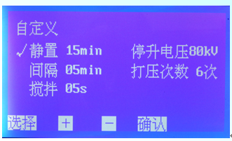
Figure 5 custom settings sub page
Under the page in Figure 5 , press the Select key to move the cursor to the corresponding option, and then press the + or - key to set the related parameters. among them:
The default time for standing is 15 min , ranging from 1 to 15 min (increment Δ = 1 min );
The default interval time is 5 min , with a range of 1 to 10 minutes (incremental Δ = 1 min );
The default value of stirring time is 10 s , range 5 to 90 s (incremental Δ = 5 s );
The default value of the stop voltage is 80 kV in the range of 10 to 80 kV (increase Δ = 10 kV ). When the instrument is boosted to the stop voltage, it will stop boosting and enter the hold state. If there is no breakdown for 50 s , the instrument will default to the current stop voltage as the dielectric breakdown voltage ;
The default value of the number of pressure suppression is 6 times, and the available range is 1 to 6 times (increment Δ =1 ). After setting, press the ENTER key to return to the start page and press the start key to test;
. 7. Under the page in Figure 2 , press the Select key to move the cursor to the data calibration point. Press the Enter key to enter the Data Calibration sub-page (Figure 6 ).

Note: The factory data is factory calibrated and the user does not need to enter the program calibration. If you need calibration data, please contact the manufacturer to ask for a password for calibration.
8. Each breakdown voltage value and number of cycles are stored automatically. After the measurement is completed, the test is displayed. Press the ENTER key to return to the boot page (Figure 1 ). Press the Print or Display key to enter the single breakdown voltage value of the oil sample. The stored record of the average shows the sub-pages (Figure 7 ).

press  print  The key prints the (closest set of) test results displayed on the page. press  select  Key to enter the sub-page number data storage 1 (FIG. 8). Press again on the page in Figure 8 .  The key, enter the data storage sub-page number 2 (Figure 9 ), and so on. So, the selection of this group of sub-pages  FIG loop flip key button 8 to 12.
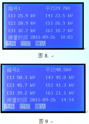
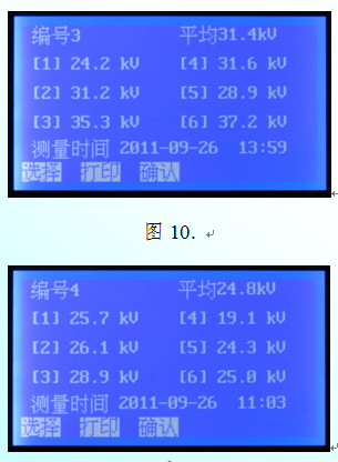
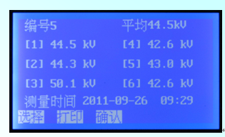
In the sub-page 8 to 12, the printing press to print the test results displayed sub-page; press OK start page (FIG. 1) is returned.
Note: The LYZJ-V Dielectric Oil Dielectric Strength Tester uses the same reverse-order data storage system as the PC . You can easily find the numbering and time sequence of the figures in Figures 8 to 12 , ie the number 1 shows the most recent The test data, while number 2 shows the most recent test data, and so on. Since the memory can store the latest 35 sets of test data, when the data exceeds 35 sets, the system will automatically replace the past data with the memory.
In the display sub-page, press the Print key to print the stored data of the selected page, press the ENTER key to return to the main page .
Seven, matters needing attention
1. Before using the instrument, be sure to read this manual thoroughly.
2. Instrument operators should be familiar with the general use of electrical equipment or analytical instruments common sense;
3. The instrument can be used indoors and outdoors, but should avoid rain, corrosive gases, high concentrations of dust, high temperature or direct sunlight and other places;
4. The oil cup should be kept clean. During decommissioning, a sufficient amount of dry insulating oil should be added to soak, to keep the cup from oxidation and oxidation of the electrode;
5. After one month of continuous use of the electrode, it should be routinely inspected and maintained. Check and adjust the electrode gap to restore the standard value; magnifier observation of the electrode surface for dark spots, if this phenomenon, use a silk cloth to wipe the electrode surface, to restore the original state;
6. The maintenance and debugging of the instrument must be completed by professionals;
7. Before turning on the power, you should carefully check whether the connection cable is firm and the instrument housing must be reliably grounded!
8. After the power is turned on, the operator is forbidden to touch the cover of the oil cup cover to avoid the risk of electric shock!
9. If the instrument is abnormal during use, it should be cut off immediately!
Eight, simple troubleshooting
1. No reaction at power-on Check if the power cord is properly plugged in and check that the fuse is intact;
2. Do not pressurize to check whether the cover of the oil cup cover is covered;
3. Normal rise but no breakdown Check if the limit of stop voltage is limited;
4. There is no display after breakdown to check whether there is dirt in the oil cup;
5. Print no paper Check if the printer has paper;
6. Replace the printer The printer has paper installed at the factory. If paper is used up, you need to install new paper yourself. Its operation is as follows:
( 1 ) Press the round button on the printer's front cover;
( 2 ) Insert the printing paper into the printer and pull out a piece of paper (beyond the paper-cutting teeth), pay attention to the paper neatly, and pay attention to the direction of the paper (after the paper is pulled out, the outside of the paper roll faces the print head);
( 3 ) Close the paper compartment cover, press the print head's paper feed shaft and press the print head's paper feed shaft back to the print head.
Oil cup cleaning:
1. Oil cup cleaning method
( 1 ) Wipe the electrode surface and electrode rod repeatedly with a clean silk cloth;
( 2 ) Adjust electrode gaps with standard gauges;
( 3 ) Wash with ethanol 3 to 4 times, then blow dry with a hair dryer. Reuse
Test oil sample can be washed 2 to 3 times;
2. Stirring pad cleaning method
( 1 ) Repeatedly wipe the paddle with a clean silk cloth until no fine particles are on the surface. Avoid direct contact with the stirring paddle by hand;
(2) forceps paddles, dipped in ethanol washing 2 to 3 times, and then dried with a dryer;
( 3 ) Hold the stirring paddles with tweezers and immerse the oil sample to be tested for washing 2-3 times.
Instrumentation
1. The equipment 1
2. 1 set of oil cup
3. Power line 1
4. a standard gauge
5. Insurance 2 ( 3A )
6. Mixing paddle 2 only
7. Tweezers 1
8. Printing Paper 1 Axis
9. Operating Manual 1
10. Warranty Card 1
11. Certificate 1
Eleven, after-sales service:
Within one year from the date of purchase, the instrument is a free warranty for product quality issues and provides maintenance and technical services for life. If it is found that the condition of the instrument is abnormal or there is a fault, please contact us in order to arrange the most convenient and effective treatment solution for you.
respected user:
Thank you for choosing LYZJ-VI Automatic Insulation Dielectric Strength Tester! In order to facilitate the skilled operation of this instrument as soon as possible as soon as possible, we have randomly assigned a detailed operation manual, from which you can obtain information on product introduction, usage, instrument performance and safety precautions and many other aspects.
Before using the instrument for the first time, be sure to read this operating manual carefully and follow this manual to operate and maintain the instrument. This will help you to use the product better and extend the life of the instrument.
Although we have worked in a scientific and rigorous manner when writing this manual, we believe that the information provided in this manual is correct and reliable. However, the wisdom of the wise is bound to be lost. The manual will also inevitably contain errors and omissions. If you find errors in the manual, please be sure to take time out of your busy schedule and try to inform us as soon as possible. Please monitor and supervise us to correct mistakes quickly! All staff of this company will be greatly appreciated!
The company reserves the right to improve the function of the instrument. If it is found that the function of the instrument during use is inconsistent with that described in the operating manual, the actual function of the instrument shall prevail. We hope this instrument will make your work easier and more enjoyable. We hope you will feel the ease and good feeling of office automation in your busy work!
When you are satisfied with the company's equipment, please recommend it to your friends! When you have valuable opinions and suggestions on this instrument, please be sure to contact us. The company will make every effort to give you a satisfactory answer. Thank you again for your support to our company!
I. Overview
LYZJ-VI type dielectric oil dielectric strength tester is all scientific and technical personnel of our company, according to the national standard GB507-86 and the line of the standard DL-474 · 4-92DL/T596-1996 relevant regulations, to play its own advantages, after many times Field trials and long-term unremitting efforts, well-developed high-precision, all-digital industrial instruments. The machine is easy to operate and beautiful in appearance. Due to the adoption of fully automatic digital microcomputer control, the measurement accuracy is high, the anti-interference ability is strong, and it is safe and reliable.
Second, the instrument features
1. The instrument is controlled by a large-capacity single-chip microcomputer and the operation is stable and reliable;
2. The device has a wide range of watchdog circuits to eliminate the crash phenomenon;
3. A variety of operating options, instrument program with GB1986 , GB2002 two national standard methods and custom operations, can adapt to a variety of different user options;
4. The instrument oil cup adopts special glass casting once to eliminate the occurrence of oil leakage and other interference phenomena.
5. The unique high-pressure sampling design of the instrument allows the test value to enter the A/D converter directly, avoiding the error caused in the analog circuit and making the measurement result more accurate;
6. The instrument has functions such as over-current protection, over-voltage protection, short-circuit protection, etc., and it has strong anti-interference ability and good electromagnetic compatibility.
7. portable structure, easy to move, both inside and outside the home is very convenient.
Third, technical indicators
1. Booster capacity 1.5 kVA
2. Boost Speed 2.0 kV / s, 2.5 kV / s, 3.0 kV / s, 3.5 kV / s optional fourth gear
3. Output voltage 0 ~ 80 kV
4. Power distortion rate < 1%
5. Display mode Large-screen LCD Chinese character display
6. Electrode Clearance Standard 2.5 mm
7. Overall dimensions 730 mm × 410 mm × 390 mm
8. Instrument weight 38 kg ( ODST-1203 )
Fourth, the use of conditions
1. Ambient temperature 0 to 40 °C
2. Relative humidity ≤ 85%
3 working power AC 220V ± 10%
4. Power frequency 50 ± 5 Hz
5. Power consumption < 200 W
V. Chassis and panel parts description
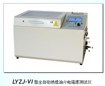
LYZJ-VI Automatic Insulation Dielectric Strength Tester
1. LCD screen; 2. Function key; 3. the printer; 4. boosting rate switching switch; 5. indicator;
6. Oil cup cover; 7. Temperature and humidity sensor; 8. Ground post; 9. Power jack; 10. Power switch; 11. High voltage safety sign

1. LCD screen        Display date, time, operating parameters, test results, operation menu prompts and other relevant information;
2. Function keys select settings operating parameters;
3. The printer prints the average of single and multiple test results;
4. switch to select different boost rates;
5. When the indicator light is on, it indicates that the relevant operation steps are in progress;
6. Put the oil cup into or out after opening the lid of the oil cup and close it before testing;
7. The temperature and humidity sensors measure Celsius and relative humidity and convert them to digital signals for display;
8. Ground column reliable ground connection column;
9. The power socket is well connected with the AC 220V 50Hz power cable;
10. The power switch controls the power of the instrument;
11. High pressure mark indicates high pressure dangerous triangle mark.
Sixth, the operation step diagram
1. Plug in the power cord, turn on the power switch, and the LCD screen displays the boot page (Figure 1 )
2. In the Figure 1 page, press  Settings  The key goes to the next page (Figure 2 );
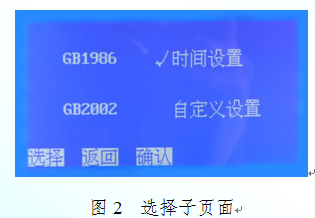
3. In the Figure 2 page, press  select  Key to move the cursor  To GB 1986 , press  confirm  The key can enter the national standard 1986 setting sub page (Figure 3 ).

  Under the page in Figure 3 , press the Select key to move the cursor to the stop voltage, press + or - to set the stop voltage  The default value is 60 kV and the selectable range is 10 kV to 80 kV (delta Δ = 10 kV ). After selecting the stop voltage, press the Select key to move the cursor to the cup position and press the Enter key to enter the cup position selection subpage (Figure 4 ).
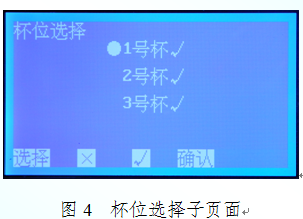
Under the page in Figure 4 , press the Select key to move the cursor to a different cup position. Press the × or √ key to define the work cup number. The default value is Select All (ie each cup position is √). Then press the confirm button to confirm the selected stop voltage and cup number and return to the boot page. Press  Start  Key to test.
If there is no reliable grounding, the instrument will show grounding! And send an alarm sound, then you should turn off the power, and then re-operation after connecting the ground. If there is no or no conditions to install the ground wire, you can press any key to skip, without affecting the test results.
4. Under the page in Figure 2 , press the SELECT button to move the cursor to the GB2002 and press the ENTER key to enter the GB 2002 setting subpage. The operation under this page is basically the same as that of the GB1986 subpage. For details , please refer to the relevant contents of Figure 6 .
5. Under the page in Figure 2 , press the Select key to move the cursor to the time setting and press the Enter key to enter the Time setting subpage (Figure 5 ).

press  select  Press the key to move the cursor to the year, month, day, hour, and minute, press the + or - key to select the specific value, press the confirmation key to confirm, and return to the boot page;
6. In the page of Figure 2 , press the Select key to move the cursor to the custom setting and press the Enter key to enter the Custom Settings sub-page (Figure 6 ).

In the Figure 6 page, press  select  Press the key to move the cursor to the corresponding option, and then press the + or - key to set the related parameters. among them:
The default time for standing is 15 min , ranging from 1 to 15 min (increment Δ = 1 min );
The default interval time is 5 min , with a range of 1 to 10 minutes (incremental Δ = 1 min );
The default value of stirring time is 10 s , range 5 to 90 s (incremental Δ = 5 s );
The default value of the stop voltage is 60 kV and the range is 10 to 80 kV in increments of = = 10 kV . When the instrument is boosted to the stop voltage, it will stop boosting and enter the hold state. If there is no breakdown for 50 s , the instrument will default to the current stop voltage as the dielectric breakdown voltage ;
The default value of the number of pressure suppression is 6 times, and the available range is 1 to 6 times (increment Δ =1 ). After setting, press the ENTER key to return to the start page and press the start key to test;
Cup position selection Press this key to enter the cup position selection sub-page. For details, see section 6. Illustration of the operation step diagram 3 .
7. For this model, parameters such as the value of breakdown voltage measured in parallel for up to 6 times per cup will be automatically stored. After the measurement is completed, the screen will show that the test is complete and give a reminder. Press the confirmation key to return to the boot page (Figure 1 ). Press the print or display key to enter the display subpage of the single measurement breakdown voltage value, arithmetic mean value, and measurement date and time of the oil sample (Figure 7 to Figure 9 ).
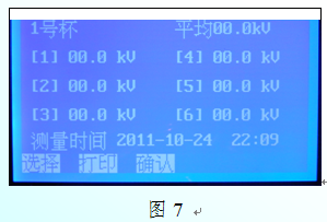
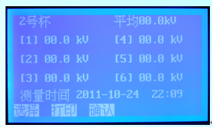
Figure 8

Figure 9
Note: In the display sub-page, press the Select key to display six interfaces in sequence. Among the first three interfaces, the data without measurement time is displayed as a temporary data group and will be lost after shutdown. The last three interfaces have measurement time data display, which is stored data group, will not be lost after shutdown. If more than three sample cups are measured, the system will group by time and the record shows the most recent three sets of data.
In the display sub-page, press the Print button to print the stored data for the selected page and press the ENTER key to return to the main page .
Seven, matters needing attention
1. Before using the instrument, be sure to read this manual thoroughly.
2. Instrument operators should be familiar with the general use of electrical equipment or analytical instruments common sense;
3. The instrument can be used indoors and outdoors, but should avoid rain, corrosive gases, high concentrations of dust, high temperature or direct sunlight and other places;
4. The oil cup should be kept clean. During decommissioning, a sufficient amount of dry insulating oil should be added to soak, so that the oil cup is protected from moisture and oxidation of the electrode;
5. After one month of continuous use of the electrode, it should be routinely inspected and maintained. Check and adjust the electrode gap to restore the standard value; magnifier observation of the electrode surface for dark spots, if this phenomenon, use a silk cloth to wipe the electrode surface, to restore the original state;
6. The maintenance and debugging of the instrument must be completed by professionals;
7. Before turning on the power, you should carefully check whether the connection cable is firm and the instrument housing must be reliably grounded!
8. After the power is turned on, the operator is forbidden to touch the cover of the oil cup cover to avoid the risk of electric shock!
9. If the instrument is abnormal during use, it should be cut off immediately!
Eight, simple troubleshooting
1. No reaction at power-on Check if the power cord is properly plugged in and check that the fuse is intact;
2. Do not pressurize to check whether the cover of the oil cup cover is covered;
3. Normal rise but no breakdown Check if the limit of stop voltage is limited;
4. There is no display after breakdown to check whether there is dirt in the oil cup;
5. Print no paper Check if the printer has paper;
6. Replace the printer The printer has paper installed at the factory. If paper is used up, you need to install new paper yourself. Its operation is as follows:
( 1 ) Press the round button on the printer's front cover;
( 2 ) Insert the printing paper into the printer and pull out a piece of paper (beyond the paper-cutting teeth), pay attention to the paper neatly, and pay attention to the direction of the paper (after the paper is pulled out, the outside of the paper roll faces the print head);
( 3 ) Close the paper compartment cover, press the print head's paper feed shaft and press the print head's paper feed shaft back to the print head.
Oil cup cleaning:
1. Oil cup cleaning method
( 1 ) Wipe the electrode surface and electrode rod repeatedly with a clean silk cloth;
( 2 ) Adjust electrode gaps with standard gauges;
( 3 ) Wash with ethanol 3 to 4 times, then blow dry with a hair dryer. Reuse
Test oil sample can be washed 2 to 3 times;
2. Stirring pad cleaning method
( 1 ) Repeatedly wipe the paddle with a clean silk cloth As a professional manfuacturer for Ejector Sleeve with high quality DIN standard H7/H5 tolerance.Producing full range of ejector sleeve size with high precision and precision tolerance.Top quality,best price and fast leadtime with SKD 61 nitrided material and hardened ejector sleeve. With a lots of experience for the OEM ejector sleeve.We have been supplied to the top brand in the world company. Ejector Sleeve Ejector Sleeve,Mold Ejector Sleeve,H5 tolerance Ejector Sleeve Injection Molding,Ejector Sleeves Catalog Changsha Borun Mould Co. Ltd. , http://www.borunmouldparts.com